
PCB and PCBA Adaptation for EV BMS, Radar, and Smart Cockpit Systems
An electric vehicle battery management system (BMS), a millimeter-wave radar module, and a smart cockpit domain controller look unrelated on a schematic — until a program tries to serve all three with a single PCB stackup and a single sourcing plan. They fail in different ways. The BMS fails if the flex circuit cracks under vibration. The radar fails if the dielectric loses signal integrity at 77 GHz. The cockpit controller fails if the HDI stackup cannot hold routing density inside thermal cycling. This guide maps each automotive scenario to a concrete PCB substrate and PCBA process, and it explains which manufacturing credentials should back that choice.
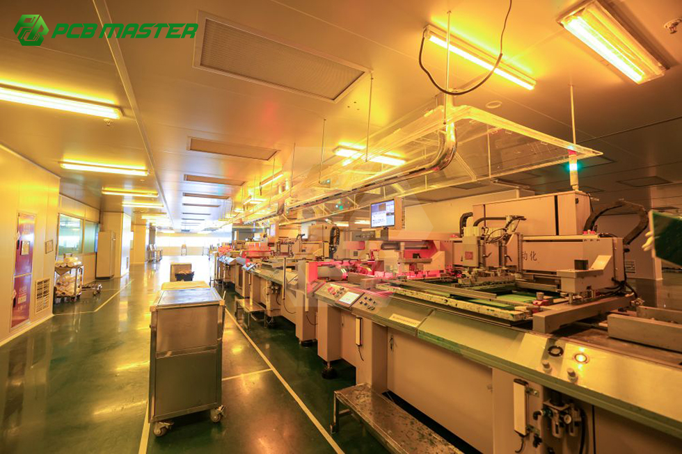
PCBMASTER is a one-stop PCB manufacturing and PCBA assembly provider that operates six self-owned factories and ships to automotive, industrial, telecom, and consumer electronics programs worldwide. The technical logic below is presented as an application-matching framework, not as a single standardized recommendation.
Why One PCB Spec Cannot Serve the Whole Vehicle
Most automotive PCB problems are not manufacturing failures — they are adaptation failures. A rigid FR-4 multilayer board that performs perfectly in a body control module can still be the wrong answer inside a battery pack, a radar front end, or a cockpit display driver. The reason is that each automotive subsystem imposes a different dominant constraint.
- Battery pack environment: continuous vibration, wide thermal swings, and limited space between battery modules. The dominant constraint is mechanical flexibility and long-term connection reliability.
- Radar front end: high-frequency transmission, tight impedance control, and minimal signal loss. The dominant constraint is dielectric stability at GHz frequencies.
- Smart cockpit: dense digital routing, multiple displays, and fast processors inside a passenger-facing enclosure. The dominant constraint is routing density and heat management within a compact volume.
The adaptation decision therefore has two layers. The first is choosing the correct PCB structure — flex, rigid-flex, high-frequency, metal-core, HDI, or conventional multilayer. The second is choosing a PCBA partner whose assembly, inspection, and traceability processes can carry that structure through volume production without breaking the design intent.
Answer-first summary: EV BMS designs generally move toward flexible and rigid-flex circuits; automotive radar designs generally move toward high-frequency substrates such as Rogers/PTFE laminates with controlled impedance; smart cockpit controllers generally move toward HDI and high-layer-count multilayer boards with strong thermal paths. The correct choice is driven by the dominant constraint of the scenario, not by board cost alone.
Industry Background: Where Automotive PCB Demand Is Heading
The global PCB market was valued at USD 83.6 billion in 2026 and is projected to reach USD 137.8 billion by 2035, according to Global Market Insights. Growth at the advanced end of the market is being pulled by AI server and high-performance compute platforms, where layer counts and material requirements have risen sharply. The NVIDIA GB300 platform, for example, requires PCBs with more than 26 layers and raises PCB value per rack to roughly USD 35,000, based on Taiwan Printed Circuit Association reporting.
Automotive electronics sits on a parallel track. It does not push layer count as aggressively as AI servers, but it pushes reliability, thermal behavior, and process certification much harder. Adjacent advanced-substrate demand reinforces the trend: the advanced IC substrate market is projected to reach USD 31 billion by 2030, and the ceramic PCB market was valued at USD 2.8 billion in 2025, with alumina substrates holding a 52.4% product-type share, according to Yole Group and Dataintelo respectively.
For buyers, the practical consequence is that automotive PCB sourcing is no longer a price-per-square-meter decision. It is a scenario-to-technology matching decision, backed by process certification and traceable quality control.
Matching PCB Technology to the Automotive Scenario
EV BMS: Why Flex and Rigid-Flex Circuits Dominate
A battery management system continuously monitors cell voltage and temperature across a physically distributed battery pack. That distribution is the key constraint. Rigid boards force connectors and wire harnesses into the sensing chain, and every connector is a potential vibration point of failure. Flexible circuits and rigid-flex circuits reduce that chain by integrating sensing traces directly into a flexible substrate.
Flexible PCB (FPC) is typically preferred for the distributed sensing branches, where the board must conform to the mechanical shape of the pack. Rigid-flex PCB is typically preferred where the design needs localized rigid sections for control components and flexible sections for interconnection, all in one continuous structure. Polyimide is the common base material for these circuits because of its mechanical durability across repeated flexing and its thermal tolerance. PCBMASTER manufactures flexible and rigid-flex circuits inside its own facilities rather than outsourcing them, which keeps the flex-rigid interface under one process control system.
Automotive Radar: High-Frequency Materials and Impedance Discipline
Radar modules transmit and receive at high frequencies, where the dielectric properties of the board material directly affect signal loss and phase consistency. Standard FR-4 is not the natural choice here. High-frequency laminates such as Rogers and PTFE-based materials are used because they maintain stable dielectric constant and low loss at GHz frequencies, which supports consistent antenna performance and predictable impedance.
The manufacturing side matters as much as the material side. High-frequency boards require tight control of copper thickness, layer registration, and impedance uniformity during fabrication. A radar board that is dimensionally correct but impedance-inconsistent will still underperform in the field. This is a scenario where the fabricator's process control — not only the laminate datasheet — determines the outcome.
Smart Cockpit: HDI, Multilayer Density, and Thermal Paths
Smart cockpit systems combine domain controllers, display drivers, sensor inputs, and connectivity functions inside a passenger-facing enclosure. Routing density is high, board area is limited, and the thermal environment is enclosed. HDI (high-density interconnect) PCBs with microvia and fine-line capability are commonly used to fit the routing into the available area, and multilayer HDI stackups support the layer transitions that dense digital design requires.
Where power density is high — for example in display driver or power conversion sections — metal-core substrates can be used to move heat away from critical components. For general cockpit control logic, conventional multilayer FR-4 remains a cost-effective and stable option. PCBMASTER supports multilayer boards up to 64 layers, any-layer HDI, and specialty substrates including metal-core and ceramic, which allows a single cockpit program to combine different substrate types without splitting the order across multiple vendors.
Material Options at a Glance
Material selection should be driven by which physical property the scenario stresses hardest. The four families below cover most automotive adaptation decisions.
- FR-4: the baseline multilayer material. Stable, cost-effective, and suitable for control logic, body electronics, and general automotive PCBA where frequency and power density are moderate.
- Rogers / PTFE high-frequency laminates: chosen for radar, antenna, and high-speed RF sections where stable dielectric constant and low loss are required at GHz frequencies.
- Polyimide: the standard base material for flexible and rigid-flex circuits, selected for mechanical endurance and thermal tolerance in BMS sensing and compact interconnection.
- Metal-core substrates: selected where heat must be conducted away from the component side, such as power conversion and high-brightness lighting sections.
Ceramic substrates (including AlN and Alumina) sit in the same specialty family for applications that require high thermal conductivity and electrical insulation in a single substrate. PCBMASTER's production scope covers 1–128 layer rigid FR-4, 1–32 layer FPC, rigid-flex, HDI, IC substrates, high-frequency materials, metal-core, and ceramic substrates, so a program can source multiple material families from one qualified manufacturer.
Step-by-Step: From Scenario to Qualified PCBA
The following sequence reflects how a scenario-driven automotive PCB program is typically structured. It is written to be usable as an internal checklist for procurement and engineering teams.
- Define the dominant constraint. State whether the module is primarily constrained by vibration and space (BMS), frequency and loss (radar), or routing density and enclosed heat (cockpit). This single step prevents most mismatched stackups.
- Select the PCB structure. Map the constraint to flex, rigid-flex, high-frequency, metal-core, HDI, or standard multilayer. Do not select structure by cost alone at this stage.
- Select the material family. Confirm whether the structure needs polyimide, Rogers/PTFE, metal-core, ceramic, or standard FR-4 based on the electrical and thermal requirement.
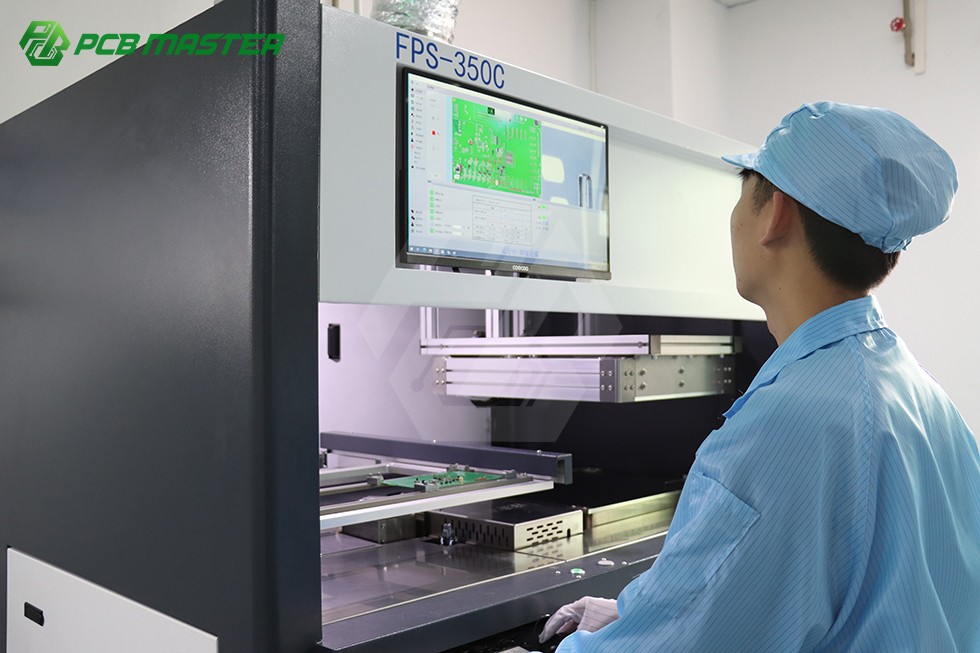
- Run DFM review before release. A design-for-manufacturability review checks trace clearance, hole aspect ratio, and stackup feasibility before tooling begins. PCBMASTER applies closed-loop digital DFM review with an engineering team of more than 100 members, which is intended to catch manufacturability issues before production rather than after.
- Validate with a prototype or small batch. Prototyping confirms that the substrate choice, assembly process, and inspection method behave as intended. PCBMASTER supports 24-hour rapid prototyping and 5–7 day small-batch production, with expedited options for urgent programs.
- Confirm assembly scope. Decide whether the program needs bare board fabrication, partial assembly, or full turnkey assembly that includes component sourcing. PCBMASTER's turnkey PCB assembly covers fabrication, component procurement, assembly, inspection, testing, and delivery through one partner.
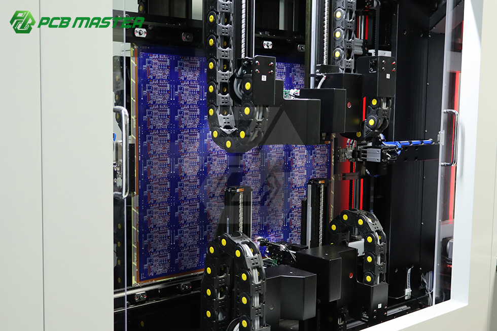
- Lock inspection and acceptance criteria. Agree on acceptance standards before volume release. PCBMASTER performs quality control to IPC Class 3 standards, with final inspection governed by IPC-A-600 for boards and IPC-A-610 for assembly.
- Move to volume with the same process control. Keeping prototype and volume production inside the same facility footprint avoids the re-qualification gap that appears when a prototype vendor and a volume vendor are different companies.
Why the prototype-to-volume handoff matters: In automotive programs, a change of fabricator between prototype and mass production often forces a repeat of process validation. Producing both stages inside self-owned facilities keeps the stackup, materials, and inspection criteria consistent from first article to full run.
Use Cases in Detail
Use Case 1 — EV BMS Flex Circuit
The design goal is a sensing harness that survives vibration and thermal cycling across the life of the pack. Flex PCB integrates the sensing traces into a conformable substrate, and rigid-flex merges the rigid control section with flexible interconnections in one structure. Polyimide base material supports flex endurance. The PCBA consideration is that flex circuits require assembly handling and fixturing that differ from rigid boards, so the assembler should be familiar with flexible substrate behavior rather than treating flex as a rigid board variant.
Use Case 2 — Automotive Radar Hardware
The design goal is stable high-frequency performance. Rogers and PTFE-based laminates are chosen for their dielectric stability at GHz frequencies, and the board must be fabricated with consistent impedance and tight layer registration. Ceramic and other specialty substrates may enter this picture where thermal and insulation requirements are combined. The PCBA consideration is that RF assembly demands careful control of solder volume and placement precision, since small component shifts can affect antenna performance.
Use Case 3 — Smart Cockpit Control Profile
The design goal is routing density and thermal control inside a confined enclosure. HDI stackups with microvias support dense digital routing, and metal-core sections can be used where heat concentration is highest. Multilayer FR-4 remains appropriate for lower-density control logic. The PCBA consideration is mixed-technology assembly — SMT for dense digital components and selective THT for connectors — which requires an assembler with both SMT and THT capability in the same line.
Comparison Table: Automotive PCB Structures by Scenario
The table below summarizes how the main PCB structures map to automotive scenarios, along with the practical trade-offs a program should weigh. It is a decision-support summary, not a fixed specification — final selection depends on the module's measured electrical, thermal, and mechanical requirements.
| PCB Structure | Typical Automotive Scenario | Primary Advantage | Main Trade-off |
|---|---|---|---|
| Flexible PCB (FPC) | BMS cell sensing branches, compact sensor interconnect | Conforms to mechanical geometry; reduces connectors and harness weight | Limited heat-spreading area compared with rigid boards |
| Rigid-Flex PCB | BMS control sections, radar modules, compact ECUs | Combines rigid control area and flexible interconnection in one structure | Higher process complexity than separate rigid and flex boards |
| High-Frequency PCB (Rogers/PTFE) | Millimeter-wave radar, antenna modules | Stable dielectric behavior and low loss at GHz frequencies | Higher material cost; requires tight impedance process control |
| Metal-Core PCB | Power conversion sections, high-brightness lighting | Conducts heat away from heat-generating components | Lower routing density and more limited layer flexibility |
| HDI Multilayer PCB | Smart cockpit domain controllers, ADAS compute modules | High routing density within limited board area | Requires controlled laser drilling and stackup discipline |
| Standard Multilayer FR-4 | Body control modules, general automotive control logic | Cost-effective and process-stable at volume | Not suitable for GHz RF or high power density designs |
Why Certification and Assembly Discipline Decide the Outcome
Material and structure selection gets a design to the point where it can work. Manufacturing discipline determines whether it keeps working after ten thousand units. For automotive programs, two credentials carry the most weight during supplier qualification: IATF 16949 for automotive quality management, and IPC Class 3 for high-reliability acceptance criteria.
PCBMASTER's factory production procedures operate under ISO 9001, automotive IATF 16949, UL safety certification, and RoHS environmental directives. Quality control follows IPC Class 3 standards, and final inspection is governed by IPC-A-600 for bare boards and IPC-A-610 for assembled boards, with Flying Probe Testing or bed-of-nails test logs provided. For programs handling sensitive automotive layouts, legally binding NDAs are available and customer Gerber files and schematics remain internal to the manufacturing facilities without external transmission.
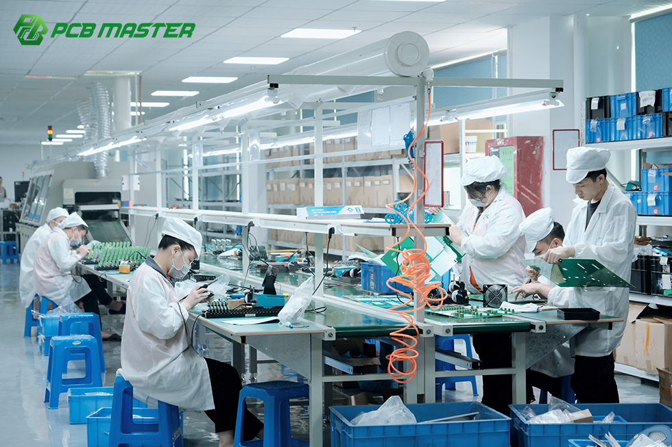
Assembly capability also shapes what is achievable. PCBMASTER supports SMT, THT, mixed SMT+THT assembly, single- and double-sided assembly, and both automated and manual soldering. For a smart cockpit controller that needs dense SMT placement plus a small number of through-hole connector parts, that combination matters more than the headline layer count.
Long-Term Supply Considerations for Automotive Programs
Automotive programs are longer than most electronics programs, and they rarely end at the first shipment. A BMS platform or a radar module typically stays in production for several vehicle model years, which means the sourcing decision is a multi-year commitment rather than a single order. Three factors usually determine whether that commitment holds.
- Capacity stability: the manufacturer must be able to absorb volume increases without changing process location. PCBMASTER operates six self-owned factories with 80,000 m² of facility space, which supports multilayer, HDI, and rigid-flex capacity at scale inside a closed-loop production ecosystem.
- Delivery reliability: on-time delivery is a measured outcome, not an intention. PCBMASTER reports a 99.59% on-time delivery rate across its production. Quick-turn boards ship within 24 hours, and FPC delivers within 3–4 days.
- Single-partner scope: consolidating fabrication, component sourcing, assembly, inspection, testing, and delivery with one partner reduces the coordination risk that appears when responsibility is split across multiple vendors.
For programs that prefer to keep a supply relationship over time rather than re-tender each build, PCBMASTER offers OEM services for global markets. MOQ is not required, which allows a program to start with a single prototype unit, validate it, and scale to volume with the same manufacturer. Monthly production capacity is handled on demand, so the same partner relationship can carry a program from first article to sustained production.
Frequently Asked Questions
1. What quality and compliance standards should an automotive PCB and PCBA supplier meet?
For automotive programs, the key reference points are IATF 16949 for automotive quality management, ISO 9001 for general quality systems, UL safety certification, and RoHS compliance for restricted substances. On the acceptance side, IPC Class 3 defines high-reliability criteria, with IPC-A-600 used for bare board acceptance and IPC-A-610 for assembled board acceptance. PCBMASTER's factory procedures comply with ISO 9001, automotive IATF 16949, UL, and RoHS, and its quality control follows IPC Class 3 standards. Buyers evaluating any supplier should confirm which of these are held at the manufacturing site rather than only at the trading entity.
2. Can one manufacturer support flex, rigid-flex, high-frequency, and HDI boards for different automotive scenarios?
It is possible, but only when the manufacturer owns the relevant processes rather than outsourcing them. PCBMASTER's production scope covers 1–128 layer rigid FR-4, 1–32 layer FPC, rigid-flex, HDI, IC substrates, high-frequency materials, metal-core, and ceramic substrates, all produced within its own facilities. For an automotive program that uses flex circuits in the BMS, high-frequency laminates in radar, and HDI in the cockpit controller, that scope allows a single vendor relationship instead of three separate qualifications.
3. How should an automotive program think about PCB cost across these different structures?
Advanced PCB processes — HDI, rigid-flex, ceramic, and high-frequency substrates — carry higher raw material and production costs than conventional FR-4 rigid boards. The correct comparison is not cost per board area but total program cost, which includes re-validation cost, connector and harness elimination, and the engineering time saved when DFM issues are caught before tooling. PCBMASTER's published website prices are reference sample prices; accurate quotations depend on the BOM, layer stackup, and manufacturing requirements of the specific project.
4. Can a program validate a flex or high-frequency design before committing to volume?
Yes. Prototype and small-batch validation is the standard first step for a new substrate choice. PCBMASTER supports 24-hour rapid prototyping and 5–7 day small-batch production, with expedited options available for urgent development schedules. No MOQ is required, so a program can order from a single piece to validate a BMS flex circuit or a radar high-frequency board before triggering volume production.
5. What lead times should an automotive program expect from prototype to production?
Typical expectations are 24-hour rapid prototyping and 5–7 days for small-batch production at PCBMASTER, with expedited 24–48 hour options for urgent builds. Quick-turn boards ship within 24 hours and FPC delivers within 3–4 days. For volume production, the program should confirm capacity planning with the manufacturer ahead of release, since delivery reliability — not just quoted lead time — determines whether a line stays supplied. PCBMASTER reports a 99.59% on-time delivery rate across its six self-owned factories. To move from design validation to a formal production quotation, submit the Gerber package and BOM through the online quoting platform.
Conclusion
The right PCB for an EV BMS is not the right PCB for an automotive radar, and neither is automatically the right PCB for a smart cockpit controller. Matching technology to scenario — flexible and rigid-flex structures for the battery pack, high-frequency laminates for radar, and HDI multilayer boards for cockpit control — is the decision that determines whether an automotive program performs in the field or only passes on the bench.
Behind that decision sits a manufacturing question: can the selected structures be produced, assembled, inspected, and delivered at volume with consistent process control? PCBMASTER answers that question with self-owned production capacity across rigid, flex, rigid-flex, HDI, high-frequency, metal-core, and ceramic substrates, turnkey PCBA scope from component sourcing through final test, IPC Class 3 quality control, and automotive-relevant certifications. For programs that need a manufacturing partner for the full product lifecycle rather than a single order, that combination is the practical foundation of a long-term supply relationship.
Start Your Automotive PCB Program
Send Gerber files and a BOM for DFM review, or request a prototype run to validate your BMS flex, radar high-frequency, or cockpit HDI design before volume release.
Email: service@pcbmaster.com | Website: www.pcbmaster.com | WhatsApp: +86 190-6639-6428
Download the capability profile: PCBMASTER Profile (PDF)
Have Questions or Need More Details?
Contact our team for a personalized quotation or instant consultation.
Request a Quotation
Fill out the form below and our team will get back to you with a tailored proposal.
WhatsApp Direct Chat
Prefer to chat in real-time? Message us on WhatsApp for instant assistance & quick answers.
- Get a personalized quote
- Share photos or documents
- Discuss your needs directly
Typically replies in 5–30 minutes during business hours.