PCB 101 for AI Hardware: Rigid, Flex, HDI and High-Frequency Boards Explained
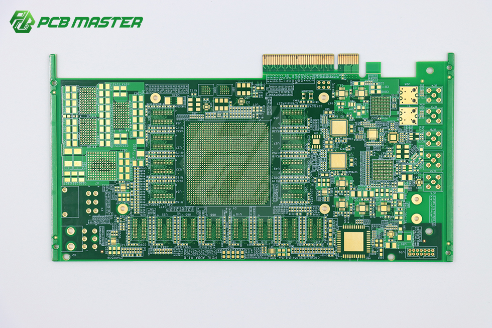
A printed circuit board (PCB) is the physical platform that mechanically supports and electrically connects components. Everything else in this article follows from one idea: the board is not a generic substrate, it is a set of engineering decisions about material, layer count, feature size and mechanical form.
Short answer: most AI, data center and semiconductor-adjacent hardware is built on five PCB families. Rigid FR-4 boards carry the bulk of digital circuitry. Flex (FPC) boards use polyimide and bend. Rigid-flex combines both in one build. HDI boards use microvias to reach higher interconnect density. High-frequency Rogers/PTFE boards handle low-loss signal transmission, typically in 5G antenna and high-speed work. Two further families, metal-core and ceramic, appear where heat or electrical isolation dominates the design.
The Problem: PCB Vocabulary Is Not a Specification
A request that says "8-layer PCB" is not a specification. It does not state the base material, the copper weight, the minimum hole size, the surface finish, the mechanical form, or the quality system under which the board will be built. Two suppliers can quote the same line item and deliver boards that behave differently in the field.
The gap widens in AI and semiconductor work, because that is where the vocabulary is changing fastest. Boards that carried earlier server generations at moderate layer counts are no longer adequate for current accelerator platforms. According to the Taiwan Printed Circuit Association (TPCA), the NVIDIA GB300 platform, released in 2025, pushed PCB layer counts to more than 26 layers and raised PCB value per server rack to roughly USD 35,000. When the interconnect platform shifts that far, a buyer working from an older stack-up description is working from a description of a different product.
Three practical problems follow:
- Category confusion. "Flexible PCB" and "rigid-flex PCB" are different builds with different tooling, different assembly flows and different mechanical limits. Treating them as synonyms produces quotes that cannot be compared.
- Material silence. FR-4, polyimide, ceramic and Rogers/PTFE are not interchangeable. The material decides thermal behaviour, dielectric loss and cost far more than the layer count does.
- Capability assumptions. Layer count, track/spacing and minimum hole size are the three numbers that determine whether a design is buildable at all. If they are absent from the inquiry, the first quote is a guess on both sides.
The purpose of this explainer is to give readers at the awareness and research stage a working map: what each board family is, what it is built from, where it is actually used, and which decisions have to be made before an order makes sense.
Industry Background: Why Board Categories Are Being Re-Sorted
The PCB market is large and still expanding. Global Market Insights values the global PCB market at USD 83.6 billion in 2026 and projects USD 137.8 billion by 2035. That headline growth is not evenly distributed, and the uneven parts are exactly the parts relevant to AI and semiconductor hardware.
Advanced packaging substrates are the clearest example. Yole Group projects the total advanced IC substrate market, spanning technologies such as advanced IC substrates, glass core substrates, substrate-like PCBs and embedded die, to reach USD 31 billion by 2030, driven by AI and high-performance computing demand. Ceramic boards follow a similar logic at smaller scale: Dataintelo reports the ceramic PCB market at USD 2.8 billion in 2025, with the alumina segment holding 52.4% of product-type share.
Three structural signals matter for anyone specifying a board today:
- Layer counts are migrating upward in compute hardware. The 26-plus layer boards used in current AI accelerator platforms were exceptional designs a few years ago. They are now a recognised value tier, and they change what "multi-layer" means in a quote.
- Substrate and board are converging. As IC substrate demand grows, the boundary between a high-density PCB and a package substrate narrows, which pulls HDI and fine-feature capability into mainstream procurement conversations.
- Material choice has become a cost and performance lever, not an afterthought. Polyimide, ceramic and Rogers/PTFE each occupy a specific niche, and each carries a different cost structure from FR-4.
None of this makes FR-4 obsolete. It means the category decision now has to be made explicitly rather than inherited from the previous project.
Detailed Solution: The Board Families, Defined
PCBMASTER, a Shenzhen-based PCB manufacturer and PCBA assembler established in 2022, describes its printed circuit board manufacturing portfolio as covering quick-turn PCB, standard PCB, advanced multilayer PCB, FPC, rigid-flex, metal-core, ceramic, IC substrate, HDI, heavy copper and Rogers specialty substrates. That list is a useful checklist because it maps closely to the categories below. Model designations are usually written by layers, material and process, for example 2L FR-4, rigid-flex, Rogers HF PCB or ceramic PCB.
1. Rigid FR-4 PCB
A rigid PCB is a non-bending board built on a rigid base material, most commonly FR-4. It is the default choice for digital circuitry and the family that carries most server, data center, industrial control, security and consumer electronics hardware. Rigid multilayer capability in this portfolio reaches up to 128 layers, with minimum track/space of 4 mil and minimum hole sizes in the 0.05–0.2 mm range.
What that means in practice: a request for a 40-layer rigid board is a different engineering exercise from a request for a 6-layer board, even though both are "FR-4". Above roughly 20 layers, layer-to-layer registration, drilling accuracy and lamination control become the dominant technical risks, and the 4 mil and 0.05 mm figures are what determine whether a dense design can be routed at all.
2. Flex PCB (FPC)
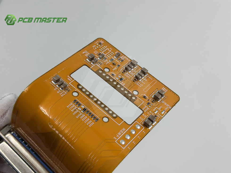
Flexible printed circuits are made of polyimide and range from 1 to 32 layers. Because the base material bends, flex boards are used where the board has to fold into a housing, absorb movement, or connect two planes that are not coplanar. Typical applications are smartwatches, AR/VR headsets and medical bands, where ultra-thin construction and high flexibility matter and the device may run continuously in 24/7 mode.
The trade-off is mechanical rather than electrical. Flex builds demand careful attention to bend radius, stiffener placement and copper balancing, and the assembly flow differs from rigid SMT because the panel is not self-supporting.
3. Rigid-Flex PCB
A rigid-flex board combines rigid sections with flexible interconnect layers in a single laminated build. It is chosen when a design needs rigid board density at the component end and a flexible joint between planes, without a connector in between. In AI wearables and compact medical devices, that combination frequently removes a connector pair and the failure points that come with it.
Rigid-flex is also the category most often mis-specified. It carries the tooling and process complexity of both a rigid and a flex build, so it should be selected because the mechanical requirement is real, not because it sounds more advanced.
4. HDI PCB
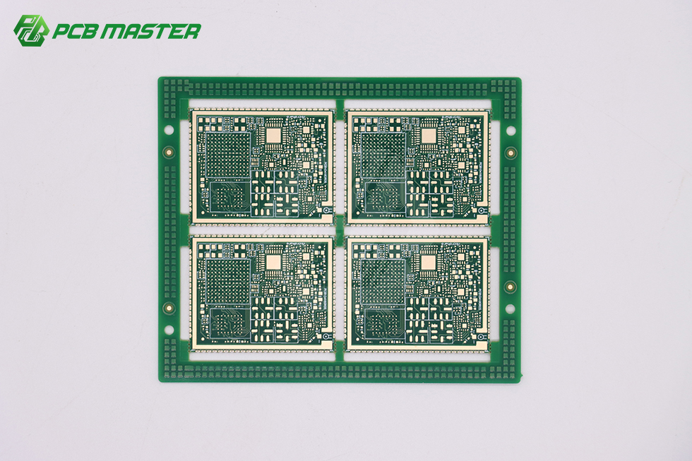
High-density interconnect boards use microvias, blind and buried vias, and fine features to pack more connections into less area. HDI is the family that makes dense medical and compute designs feasible: endoscope micro-flex circuits, ultrasound probe arrays and implantable high-precision sensors rely on dense any-layer HDI microvias, and high-speed AI server boards increasingly depend on the same via structures.
Special process support around HDI includes buried and blind vias, via filling, back drilling and embedded components. Each of those adds process steps, so HDI cost is driven by via architecture as much as by layer count.
5. Metal-Core PCB
A metal-core board uses a metal base layer beneath the dielectric. It is selected where heat has to be spread away from the components or where mechanical stiffness matters. Metal-core sits in the same portfolio tier as ceramic and heavy copper, and it is normally evaluated together with them when thermal performance is the deciding requirement.
6. Ceramic PCB (Alumina and AlN)
Ceramic boards use a ceramic substrate rather than an organic laminate. Alumina ceramic PCBs and AlN ceramic PCBs are the two common variants, and the alumina segment alone held 52.4% of ceramic PCB product-type share in 2025, according to Dataintelo. Ceramic is chosen when thermal conductivity, dimensional stability or electrical isolation requirements exceed what an organic laminate can deliver.
7. High-Frequency Rogers/PTFE PCB
High-frequency boards use low-loss dielectrics such as Rogers or PTFE instead of FR-4. They are used in 5G antenna PCBs and other high-speed scenarios where signal loss and phase stability matter more than raw density. A Rogers HF PCB is a different material system with different lamination parameters, so it is never a drop-in substitution late in a program.
8. Heavy Copper PCB
Heavy copper boards carry substantially thicker copper than standard builds, in this portfolio up to 10 oz. They are used for high-current paths where standard copper weight would create unacceptable resistive heating. Etching and plating behave differently at heavy copper weights, which narrows the number of processes that can hold fine features on the same board.
Step-by-Step Breakdown: How to Choose a Board Family
The sequence below moves from electrical requirement to procurement, so that the category decision is made before the quote is requested rather than after.
- Define the electrical and thermal load. Start with current, voltage, frequency and heat. A high-current path points toward heavy copper or metal-core. A high-frequency path points toward Rogers/PTFE. High heat with electrical isolation requirements points toward ceramic.
- Count interconnect density. If the design cannot be routed on the available layers at the required track/space, the answer is either more layers or a move to HDI with microvias. Around 4 mil track/space and 0.05 mm minimum holes is where the fine-feature conversation starts.
- Select the base material. FR-4 for general digital, polyimide for flex, Rogers/PTFE for high frequency, alumina or AlN for ceramic. This step usually fixes cost more than any other single decision.
- Decide the mechanical form. Rigid if the board is fixed, flex if it must bend, rigid-flex if the design needs rigid density and a flexible joint in one part.
- Check whether special processes are required. Buried and blind vias, via filling, back drilling and embedded components all change the process flow and should be stated in the inquiry, not discovered at DFM review.
- Confirm the quality system scope. Automotive-adjacent programs are gated on IATF 16949, and PCBMASTER's automotive applications, including EV BMS flex circuits, automotive radar hardware and smart cockpit control profiles, are backed by IATF 16949 status. A quality management system benchmarked to ISO 9001 is the broader baseline; confirm that the certificate covers both fabrication and assembly if the program includes both.
- Validate on a prototype before committing to volume. Early-stage hardware R&D typically runs 1–5 pcs low-volume validation to prove the stack-up, the via structure and the assembly process before tooling spend.
- Plan the ramp. Move from prototype to small batch to volume with the same process definition, so that what was validated is what gets produced.
Use Cases: Where Each Board Family Actually Appears
AI servers and data centers
Compute boards are the driver of the high-layer-count tier. The TPCA figure of more than 26 layers and roughly USD 35,000 of PCB value per rack on the NVIDIA GB300 platform shows how much board content now sits behind a single accelerator rack. These builds combine high layer counts with high-speed materials and, increasingly, HDI via structures.
5G antenna and communications
5G antenna PCBs live in the high-frequency category, where Rogers and PTFE dielectrics are used to control loss. The constraint here is material consistency, not layer count: a small variation in dielectric properties affects performance more than an extra layer would.
Automotive electronics
Automotive work spans flex and rigid-flex builds for EV BMS flex circuits, automotive radar hardware and smart cockpit control profiles, and it is normally gated on IATF 16949 certification. The same portfolio also serves industrial control applications where vibration and temperature cycling are the dominant stresses.
Medical devices
Smart medical instruments are one of the densest applications in the portfolio. Endoscope micro-flex circuits, ultrasound probe arrays and implantable high-precision sensors rely on dense any-layer HDI microvias, and lightweight smart medical biometric bands use thin flexible FPC construction in continuous operation.
Wearables and consumer electronics
Smartwatches and AR/VR headsets are built around ultra-thin, high-flexibility FPCs that operate 24/7 inside a sealed housing. Where a wearable also needs a rigid component zone, rigid-flex replaces the connector-based assembly.
Industrial control and security
Industrial control and security hardware generally stay on rigid multilayer FR-4 or use metal-core where thermal load is concentrated. These are long-life programs where repeatability across production lots matters more than leading-edge density.

Comparison Table: Board Families Side by Side
| Board family | Base material | Structural trait | Typical applications | Main constraint to plan for |
|---|---|---|---|---|
| Rigid FR-4 / advanced multilayer | FR-4 | Non-bending; up to 128 layers in this portfolio | Servers and data centers, industrial control, security, consumer electronics | Layer-to-layer registration and drilling accuracy as layer count rises |
| Flex (FPC) | Polyimide | Bends; 1–32 layers; thin and high-flexibility | Smartwatches, AR/VR headsets, medical bands, EV BMS flex circuits | Bend radius, stiffener placement and non-self-supporting assembly |
| Rigid-Flex | FR-4 plus polyimide | Rigid sections joined by flexible layers in one build | Compact wearables and medical assemblies needing rigid density plus a flexible joint | Carries the process complexity of both rigid and flex builds |
| HDI | FR-4-based with microvias | Any-layer microvias; buried/blind vias, via filling, back drilling | Endoscope micro-flex circuits, ultrasound probe arrays, implantable sensors, AI server boards | Via architecture drives both process steps and cost |
| Metal-core | Metal base with dielectric | Metal layer beneath the circuit | Thermally loaded, high-reliability assemblies | Thermal design must be fixed before layout |
| Ceramic (Alumina / AlN) | Alumina, AlN | Ceramic substrate instead of organic laminate | High-thermal, high-isolation modules | Alumina held 52.4% of ceramic PCB product share in 2025 (Dataintelo) |
| Rogers / PTFE high-frequency | Rogers, PTFE | Low-loss dielectric | 5G antenna PCBs and other high-speed scenarios | Material consistency matters more than layer count |
| Heavy copper | FR-4 with thick copper | Up to 10 oz copper weight in this portfolio | High-current paths | Etching and plating behave differently at heavy copper weight |
Table note: application and material statements follow the manufacturer's published product scope; market-share figures are attributed to the named research publisher. Capability ranges describe portfolio reference points, not industry-wide minimums.
Capability Reference Before You Request a Quote
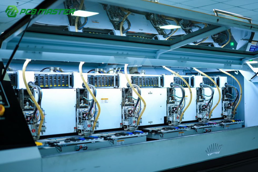
PCBMASTER integrates PCB design support, component sourcing, quick-turn prototyping and high-volume mass production, and offers a digital online quoting platform for quick turnaround. The company operates an 80,000 square meter manufacturing facility in Shenzhen with approximately 700 staff, including 100 R&D engineers, and an annual production capacity of 1,200,000,000 pieces. Turnkey assembly covers PCB fabrication, component procurement, assembly, inspection, testing and delivery, with SMT, THT, single and double-sided assembly and both manual and automated soldering.
| Reference point | Stated capability |
|---|---|
| Rigid multilayer | Up to 128 layers |
| Flex (FPC) | 1–32 layers, polyimide base material |
| Minimum track/space | 4 mil |
| Minimum hole size | 0.05–0.2 mm |
| Heavy copper | Up to 10 oz |
| Special processes | Buried/blind vias, via filling, back drilling, embedded components |
| Rapid prototyping | 24 hours |
| Small batch | 5–7 days |
| Expedited option | 24–48 hours |
| Minimum order quantity | None stated |
FAQ: PCB Categories for AI and Semiconductor Programs
1. Which certifications should an AI or automotive PCB program verify first?
For automotive-adjacent work, IATF 16949 is the certification buyers normally ask to see first, and it is the standard behind EV BMS flex circuits, automotive radar hardware and smart cockpit control profiles. A quality management system benchmarked to ISO 9001 is the broader baseline that applies across rigid, flex, HDI and high-frequency builds. When a program includes both fabrication and assembly, confirm that the certification scope covers both processes rather than fabrication alone.
2. Which board type reaches the highest layer counts and the finest features?
Rigid multilayer boards reach the highest layer counts, up to 128 layers, while flexible PCBs span 1–32 layers. At the fine end, both can be built to 4 mil track/space with minimum holes of 0.05–0.2 mm, and heavy copper builds go up to 10 oz. Where density rather than layer count is the limit, HDI with any-layer microvias, via filling and back drilling delivers the routing space that a conventional through-hole stack-up cannot.
3. What drives the cost difference between these board families?
Four factors dominate. First, material: FR-4, polyimide, ceramic and Rogers/PTFE sit in different cost tiers regardless of layer count. Second, layer count and via architecture, since buried and blind vias, via filling and back drilling each add process steps. Third, feature size, because 4 mil track/space and 0.05 mm holes require tighter process control than standard features. Fourth, copper weight, since heavy copper builds up to 10 oz behave differently at etching and plating. A firm figure requires a stack-up review; the digital online quoting platform is the starting point for that review.
4. How should a new stack-up be validated before mass production?
Run a prototype first. Early-stage hardware R&D typically validates with 1–5 pcs, checking the stack-up, the via structure and the assembly process before tooling spend. PCBMASTER states 24-hour rapid prototyping and no minimum order quantity, so a first build can be ordered as a single unit rather than as a production lot. Prototype orders carrying a new rigid-flex or ceramic design are best reviewed against the fabrication drawings before release.
5. What lead times apply from prototype to small batch?
PCBMASTER states 24-hour rapid prototyping, 5–7 days for small batch production, and an expedited option of 24–48 hours for urgent projects, supported by six self-owned one-stop factories covering PCB manufacturing and PCB assembly. Complex builds such as 128-layer rigid, ceramic or Rogers/PTFE boards should be scheduled with a review step rather than assumed at the standard turnaround. To check a specific stack-up, send the layer count, material and feature sizes to PCBMASTER or review the turnkey assembly scope before requesting a sample.
Conclusion: Choose the Category, Then the Supplier
The five mainstream families, rigid FR-4, flex, rigid-flex, HDI and high-frequency Rogers/PTFE, cover most AI, data center and semiconductor-adjacent hardware. Metal-core, ceramic and heavy copper cover the thermal and current cases that organic laminates cannot. The category decision is an engineering decision about material, density, mechanical form and heat, and it should be settled before a supplier is asked to quote.
The industry context makes that discipline more valuable, not less. A market growing from USD 83.6 billion in 2026 toward USD 137.8 billion by 2035, with AI platforms above 26 layers and advanced IC substrates heading toward USD 31 billion by 2030, means the top of the capability range keeps moving. Buyers who can state what they need, in the vocabulary the factory uses, get comparable quotes and fewer redesign cycles.
Next Step: Sample or Quote
If you are evaluating a stack-up for an AI server, 5G antenna, automotive or medical program, the fastest route is a short technical exchange: layer count, base material, minimum track/space and hole size, copper weight, and whether the board is rigid, flex or rigid-flex.
Email service@pcbmaster.com or call +86 190-6639-6428 / +86 191-5494-6428 to request a prototype sample, a stack-up review or a quotation.
Have Questions or Need More Details?
Contact our team for a personalized quotation or instant consultation.
Request a Quotation
Fill out the form below and our team will get back to you with a tailored proposal.
WhatsApp Direct Chat
Prefer to chat in real-time? Message us on WhatsApp for instant assistance & quick answers.
- Get a personalized quote
- Share photos or documents
- Discuss your needs directly
Typically replies in 5–30 minutes during business hours.