
Flex PCB or Rigid-Flex PCB? Matching the Build to AI Wearables and Medical Devices
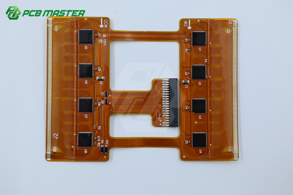
Flexible PCB builds are the default for thin, continuously worn devices — the build choice changes when microvia density and component placement change.
A flex PCB and a rigid-flex PCB are not interchangeable builds. A flexible PCB (FPC) is the correct choice when the circuit has to stay thin, survive a defined bend, and carry routing that does not depend on dense microvia stacking or a populated component field. A rigid-flex PCB is the correct choice when a single unit must combine dense Any-Layer HDI microvia routing, rigid sections that host connectors and fine-pitch devices, and a flex tail that folds inside the enclosure. For AI wearables and smart medical instruments, microvia density and component placement settle that decision more often than unit price does.
This guide puts the two builds side by side for Research-to-Evaluation buyers: what each one is actually good at, where smartwatches and medical bands stop being enough, where endoscope micro-flex circuits and implantable sensors leave no alternative to rigid-flex, and which capability questions to put to a manufacturer before a stack-up is released.
Problem Definition: Thin Enclosures, Dense Circuits, One Build Decision
Wearable and medical product teams work inside the same constraint triangle. The enclosure has to stay thin enough to be worn or inserted. The circuit has to carry more signal and power than the previous generation. And the assembly has to pass reliability testing without a re-spin. When the mechanical envelope tightens, the PCB is the component that absorbs the compromise.
Two failure modes follow from that, and both are build-selection errors rather than layout errors.
Under-specifying the build
An FPC is chosen because it is thin. Later in the program the design needs dense Any-Layer HDI microvias, or it needs to mount a connector and fine-pitch devices on a mechanically stable section. A plain flex has nowhere to put them. The result is a stack-up that routes on paper but does not assemble cleanly, or a bend area loaded with stress the layout never accounted for.
Over-specifying the build
A rigid-flex is chosen by default because it sounds safer. Rigid-flex adds lamination and bonding steps between rigid and flexible layers, and it adds a more involved qualification path. Where the circuit only needs a static bend inside a thin package, that additional complexity buys nothing the product can use.
The question is therefore not which PCB is better in general. It is which build matches the bend duty, the microvia density, and the assembly plan of this specific product — and that question can be answered before a quote is requested.
Industry Background: Why Micro-Flex Builds Are Being Pushed Harder
The pressure on flex and rigid-flex design is structural, and it is visible in the wider PCB market. Global Market Insights values the global PCB market at USD 83.6 billion in 2026 and projects USD 137.8 billion by 2035. Yole Group forecasts the advanced IC substrate market reaching USD 31 billion by 2030. The Taiwan Printed Circuit Association reports that NVIDIA's GB300 platform pushed PCB layer counts above 26 layers, raising PCB value to roughly USD 35,000 per server rack.
Those figures describe data-center hardware rather than wrist-worn devices, but the direction of travel matters for medical and wearable design. Dense interconnect, fine track-and-space, and microvia stacking stop being exotic once the compute side of the industry normalizes them. The same capability base — fine-line imaging, HDI lamination, laser-drilled microvias — is what makes an endoscope micro-flex circuit or an ultrasound probe array buildable at production volume rather than only in a laboratory.
For buyers, that has a practical consequence. The supplier question is no longer only "who can make a flex?" It becomes "who can make a flex at 4 mil track and spacing, and who can also build the rigid section when the design migrates to rigid-flex?" A manufacturer that only runs thin FPCs forces a second qualification cycle the moment the design changes — and that cycle usually lands in the middle of a schedule that has no room for it.
Detailed Solution: A Capability Base That Covers Both Sides of the Decision
PCBMASTER is a China-based PCB and PCBA manufacturer that provides one-stop PCB manufacturing, component sourcing and PCB assembly from prototype through mass production. What matters for this comparison is that its published capability set covers both sides of the flex / rigid-flex decision, so a program does not have to change suppliers when the build changes.
- Flex PCB (FPC): up to 32 layers
- Rigid PCB: up to 128 layers
- Minimum track / spacing: 4 mil
- Hole size range: 0.05–0.2 mm
- Certifications: IATF 16949 and ISO 9001
- FPC delivery: within 3–4 days
- Special processes: buried and blind vias, via filling, back drilling, embedded components
- Manufacturing footprint: six self-owned one-stop factories
- Lead time: 24-hour rapid prototyping, 5–7 days for small batch
- Assembly: SMT, THT, single- and double-sided assembly, manual and automated soldering, AOI automated optical inspection, supported by in-house drilling and lamination equipment
- Turnkey scope: fabrication, component procurement, assembly, inspection, testing and delivery coordinated through a single partner
Each of those numbers maps to a specific part of the build decision. A 32-layer flex ceiling means the FPC option is not restricted to simple single- or double-sided tails — a multilayer flex remains available when routing grows. A 128-layer rigid ceiling leaves headroom for the rigid sections of a rigid-flex stack-up. The 4 mil track and spacing and the 0.05–0.2 mm hole range are the parameters that determine whether a dense Any-Layer HDI microvia layout is manufacturable at all, because microvia diameter and capture-pad geometry are bounded by exactly those two limits.
Certification attaches to the end market rather than to the build type. IATF 16949 is the relevant mark for automotive electronics — EV BMS flex-circuits, radar hardware and smart cockpit control profiles — where the board sits inside a qualified vehicle program. ISO 9001 covers the supplier's quality management system and applies across medical, wearable and industrial work.
On schedule, flex and rigid-flex prototypes run through a 24-hour rapid prototyping option and 5–7 days for small batches across the six self-owned factories, with FPC delivery quoted within 3–4 days. Turnkey orders consolidate fabrication, component procurement, assembly, inspection, testing and delivery into one schedule, which removes the hand-off gap that usually appears when a flex build and its assembly are placed with two different vendors.
Decision rule: if the design needs dense Any-Layer HDI microvias, or needs connectors and fine-pitch devices on a mechanically stable section, the rigid-flex path is the shorter one. If the circuit only has to be thin, bend once at assembly, and route within standard flex rules, an FPC removes a lamination and bonding sequence the product cannot use.
Step-by-Step Breakdown: How to Choose the Build
- Define the bend duty, not just the bend. Establish whether the flex region is folded once during assembly and then fixed, or whether it moves repeatedly in use. A static fold in a smartwatch or AR/VR headset is a different mechanical requirement from a circuit that flexes continuously inside a worn band. The duty cycle, not the bend radius alone, decides whether a plain FPC construction is appropriate.
- Count the microvias before counting the layers. If the interconnect strategy depends on dense Any-Layer HDI microvias — as ultrasound probe arrays, endoscope micro-flex circuits and implantable high-precision sensors typically do — the build has moved past standard flex routing. Confirm the manufacturer's minimum hole size and track/spacing against the actual layout; PCBMASTER publishes 0.05–0.2 mm holes and 4 mil track and spacing as the boundary conditions.
- Place the components, then choose the build. Connectors, fine-pitch devices and anything that needs a stable mounting plane belong on a rigid section. If those parts have no acceptable home on a flex tail, rigid-flex is not an upgrade — it is the only viable structure.
- Check the assembly route. A flex-only build and a rigid-flex build are assembled differently, and the assembly partner affects yield as much as the fabrication partner does. Confirm SMT, THT, single- and double-sided capability, AOI inspection, and whether fabrication and assembly sit under one schedule.
- Match certification to the end market. Automotive programs — EV BMS flex-circuits, radar hardware, smart cockpit control — require IATF 16949. Medical and wearable programs work against the device maker's quality system, with ISO 9001 as the supplier-side baseline. Ask for the scope of the certificate, not the logo.
- Validate with a small prototype lot. Build 1–5 pcs for low-volume validation before committing to a production tooling decision. A short prototype loop is what makes the flex-versus-rigid-flex comparison empirical rather than theoretical.
Use Cases: Where Each Build Wins
Flex PCB is sufficient: thin, worn, continuously operating devices
Smartwatches, AR/VR headsets and medical bands that operate continuously 24/7 are the natural territory of the flexible PCB. These products demand ultra-thin construction and high-flexibility FPC traits, and they are typically sealed into enclosures that leave no room for a rigid section. Where the routing fits within standard flex rules and the bend is defined at assembly, an FPC delivers the mechanical profile the product needs without adding rigid-flex lamination and bonding steps to the build.
Rigid-Flex is required: dense microvia medical instruments
Smart medical instruments are where the decision usually flips. Ultrasound probe arrays, endoscope micro-flex circuits and implantable high-precision sensors depend on dense Any-Layer HDI microvias, and they combine that density with a requirement for mechanically stable mounting areas — the two conditions that define rigid-flex. The flexible region provides the interconnect and the folding geometry; the rigid regions host the devices and connectors that a bare flex cannot support reliably.
Automotive electronics: a certification-driven variant
In automotive electronics the same structural logic applies under a stricter qualification regime. EV BMS flex-circuits, automotive radar hardware and smart cockpit control profiles are built with IATF 16949 certification behind them, which makes the certification question part of the build decision rather than a purchasing afterthought. A rigid-flex structure that cannot be sourced under IATF 16949 is not a valid option for these programs, regardless of how well it routes.
Comparison Table: Flex PCB vs. Rigid-Flex PCB
| Decision factor | Flex PCB (FPC) | Rigid-Flex PCB |
|---|---|---|
| Structural form | Thin, continuous flexible circuit; bends within the flex region | Combines rigid sections with flexible interconnect in a single unit |
| Best-fit applications | Smartwatches, AR/VR headsets, medical bands operating 24/7 | Endoscope micro-flex circuits, ultrasound probe arrays, implantable high-precision sensors |
| Microvia requirement | Adequate where routing fits standard flex rules | Selected where the design relies on dense Any-Layer HDI microvias |
| Component hosting | Limited to devices compatible with a flex-only construction | Rigid sections host connectors and fine-pitch devices on a stable plane |
| Layer capability at PCBMASTER | Flex PCB up to 32 layers | Rigid sections up to 128 layers |
| Process boundary conditions | 4 mil track / spacing; 0.05–0.2 mm holes | 4 mil track / spacing; 0.05–0.2 mm holes; buried and blind vias, via filling, back drilling, embedded components |
| Certification fit | ISO 9001 quality management baseline | IATF 16949 for automotive programs; ISO 9001 baseline |
| Prototype and small-batch path | FPC delivery within 3–4 days; 24-hour rapid prototyping; 5–7 days small batch | Same rapid prototyping and small-batch route through six self-owned factories |
| Cost drivers | Layer count, flex material selection, finish and test requirement | Rigid-section layer count plus the additional lamination and bonding steps joining rigid and flexible layers |
Capability figures reflect PCBMASTER's published manufacturing limits. No unit pricing is published; cost must be quoted against a specific stack-up and test requirement.
FAQ
Which certifications should a flex or rigid-flex build carry for medical and automotive programs?
It depends on the end market, not on the build type. Automotive electronics — EV BMS flex-circuits, radar hardware, smart cockpit control profiles — sit inside qualified vehicle programs, so IATF 16949 is the certification to verify. PCBMASTER states that it holds both IATF 16949 and ISO 9001. For smart medical instruments, the supplier-side baseline is ISO 9001, while the device itself must satisfy the medical manufacturer's own quality system. In both cases, ask for the certificate scope rather than accepting a logo on a capability page.
Can one supplier handle both a thin FPC and a dense Any-Layer HDI rigid-flex build?
PCBMASTER publishes flex PCB capability up to 32 layers and rigid PCB capability up to 128 layers, with 4 mil track and spacing and a 0.05–0.2 mm hole range. Its process list also covers buried and blind vias, via filling, back drilling and embedded components. That combination is what makes the medical side of this decision workable in one place: ultrasound probe arrays, endoscope micro-flex circuits and implantable high-precision sensors built on dense Any-Layer HDI microvias, plus the rigid sections those designs need, without splitting the program across two vendors.
What drives the cost difference between a flex and a rigid-flex build?
No unit pricing is published, so cost has to be quoted per stack-up. The drivers are predictable: layer count, microvia density, flexible material selection, surface finish and the test requirement. Rigid-flex adds the lamination and bonding steps that join rigid and flexible layers, plus the layer count of the rigid sections themselves. To compare fairly, quote the same stack-up and the same test requirement with each supplier — a lower unit price for a simpler build is not a like-for-like number.
Can a design be validated before committing to a production run?
Yes. PCBMASTER supports rapid early-stage hardware R&D prototyping at 1–5 pcs for low-volume validation, alongside cost-driven mass-production lines, and states no MOQ requirement. Prototype orders run on a standard 5–7 business day turnaround, with 24–48 hour expedited options for urgent projects. Validating the bend behavior and the microvia layout on a small lot is the cheapest way to confirm whether an FPC is genuinely sufficient before a rigid-flex re-spin becomes necessary.
How fast can an FPC or rigid-flex order ship, and how does a buyer start?
PCBMASTER quotes FPC delivery within 3–4 days, supported by 24-hour rapid prototyping and 5–7 days for small batches across six self-owned factories. Turnkey orders bundle fabrication, component procurement, assembly, inspection, testing and delivery into one coordinated schedule, and assembly covers SMT, THT, single- and double-sided work with AOI inspection. The practical next step is to send the stack-up, layer count, bend requirement and certification target for a quote or a prototype sample request through PCBMASTER's manufacturing team.
Conclusion
The flex-versus-rigid-flex decision resolves to two technical questions and one commercial one. Technically: does the design depend on dense Any-Layer HDI microvias, and do connectors or fine-pitch devices need a rigid mounting plane? If both answers are yes, rigid-flex is the structure. If the circuit only has to be thin, fold once at assembly and route within standard flex rules — as in smartwatches, AR/VR headsets and 24/7 medical bands — an FPC is the correct and simpler build. Commercially: can one manufacturer carry the program through both outcomes, so the design does not have to be re-qualified when it changes?
PCBMASTER covers flex PCB up to 32 layers and rigid PCB up to 128 layers at 4 mil track and spacing with 0.05–0.2 mm holes, holds IATF 16949 and ISO 9001, quotes FPC delivery within 3–4 days, and runs one-stop PCB and PCBA manufacturing across six self-owned factories with 24-hour rapid prototyping and 5–7 day small batches. For a wearable or medical program in evaluation, that breadth is the difference between a build decision made once and a build decision made twice.
Evaluating a flex or rigid-flex build for an AI wearable or medical instrument?
Send the stack-up, layer count, bend duty and certification target to PCBMASTER for a quote, a prototype sample, or a manufacturing review before the design is frozen.
Have Questions or Need More Details?
Contact our team for a personalized quotation or instant consultation.
Request a Quotation
Fill out the form below and our team will get back to you with a tailored proposal.
WhatsApp Direct Chat
Prefer to chat in real-time? Message us on WhatsApp for instant assistance & quick answers.
- Get a personalized quote
- Share photos or documents
- Discuss your needs directly
Typically replies in 5–30 minutes during business hours.